ESP32 快速参考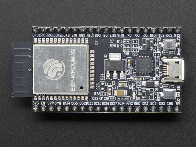 乐鑫 ESP32 开发板(图片来源:Adafruit)。 以下是基于 ESP32 的开发板的快速参考。如果这是您第一次使用该板,了解微控制器的概述可能会很有用:
安装 MicroPython请参阅教程的相应部分: 在 ESP32 上开始使用 MicroPython。它还包括故障排除小节。
通用板控制MicroPython REPL 位于波特率 115200 的 UART0(GPIO1=TX,GPIO3=RX)上。制表符补全对于找出对象具有哪些方法很有用。粘贴模式 (ctrl-E) 可用于将大量 Python 代码粘贴到 REPL 中。 该 machine 模块: - import machine
- machine.freq() # get the current frequency of the CPU
- machine.freq(240000000) # set the CPU frequency to 240 MHz
该 esp模块: - import esp
- esp.osdebug(None) # turn off vendor O/S debugging messages
- esp.osdebug(0) # redirect vendor O/S debugging messages to UART(0)
- # low level methods to interact with flash storage
- esp.flash_size()
- esp.flash_user_start()
- esp.flash_erase(sector_no)
- esp.flash_write(byte_offset, buffer)
- esp.flash_read(byte_offset, buffer)
该 esp32 模块: - import esp32
- esp32.hall_sensor() # read the internal hall sensor
- esp32.raw_temperature() # read the internal temperature of the MCU, in Fahrenheit
- esp32.ULP() # access to the Ultra-Low-Power Co-processor
请注意,由于 IC 在运行时变热,ESP32 中的温度传感器的读数通常会高于环境温度。从睡眠中醒来后立即读取温度传感器可以将这种影响降至最低。
联网该 network模块: - import network
- wlan = network.WLAN(network.STA_IF) # create station interface
- wlan.active(True) # activate the interface
- wlan.scan() # scan for access points
- wlan.isconnected() # check if the station is connected to an AP
- wlan.connect('essid', 'password') # connect to an AP
- wlan.config('mac') # get the interface's MAC address
- wlan.ifconfig() # get the interface's IP/netmask/gw/DNS addresses
- ap = network.WLAN(network.AP_IF) # create access-point interface
- ap.config(essid='ESP-AP') # set the ESSID of the access point
- ap.config(max_clients=10) # set how many clients can connect to the network
- ap.active(True) # activate the interface
连接到本地 WiFi 网络的一个有用功能是: - def do_connect():
- import network
- wlan = network.WLAN(network.STA_IF)
- wlan.active(True)
- if not wlan.isconnected():
- print('connecting to network...')
- wlan.connect('essid', 'password')
- while not wlan.isconnected():
- pass
- print('network config:', wlan.ifconfig())
一旦网络建立起来,该socket 模块就可以像往常一样用于创建和使用 TCP/UDP 套接字,以及urequests 方便的 HTTP 请求模块。 调用 后wlan.connect(),默认情况下,设备将永远重试连接 ,即使身份验证失败或没有 AP 在范围内。 wlan.status() 将返回 network.STAT_CONNECTING 此状态,直到连接成功或接口被禁用。这可以通过调用来更改 wlan.config(reconnects=n),其中 n 是所需的重新连接尝试次数(0 表示不会重试,-1 将恢复尝试永远重新连接的默认行为)。
延迟和计时使用time模块: - import time
- time.sleep(1) # sleep for 1 second
- time.sleep_ms(500) # sleep for 500 milliseconds
- time.sleep_us(10) # sleep for 10 microseconds
- start = time.ticks_ms() # get millisecond counter
- delta = time.ticks_diff(time.ticks_ms(), start) # compute time difference
计时器ESP32 端口有四个硬件定时器。将machine.Timer 类与从 0 到 3(含)的计时器 ID 一起使用: - from machine import Timer
- tim0 = Timer(0)
- tim0.init(period=5000, mode=Timer.ONE_SHOT, callback=lambda t:print(0))
- tim1 = Timer(1)
- tim1.init(period=2000, mode=Timer.PERIODIC, callback=lambda t:print(1))
周期以毫秒为单位。 此端口当前不支持虚拟计时器。
引脚和 GPIO使用 machine.Pin 类: - from machine import Pin
- p0 = Pin(0, Pin.OUT) # create output pin on GPIO0
- p0.on() # set pin to "on" (high) level
- p0.off() # set pin to "off" (low) level
- p0.value(1) # set pin to on/high
- p2 = Pin(2, Pin.IN) # create input pin on GPIO2
- print(p2.value()) # get value, 0 or 1
- p4 = Pin(4, Pin.IN, Pin.PULL_UP) # enable internal pull-up resistor
- p5 = Pin(5, Pin.OUT, value=1) # set pin high on creation
可用引脚来自以下范围(含):0-19、21-23、25-27、32-39。这些对应于 ESP32 芯片的实际 GPIO 引脚编号。请注意,许多最终用户板使用自己的临时引脚编号(标记为例如 D0、D1、...)。有关电路板逻辑引脚和物理芯片引脚之间的映射,请参阅您的电路板文档。 笔记: 引脚 1 和 3 分别是 REPL UART TX 和 RX 6、7、8、11、16、17脚用于连接嵌入式flash,不推荐用于其他用途 重复输入,也没有内部上拉搜索 引脚 34-39 仅为输入,也没有内部上拉电阻 可以设置一些管脚的pull值Pin.PULL_HOLD来降低deepsleep时的功耗。
有一个更高级别的抽象machine.Signal 可用于反转引脚。对于使用 on()或点亮低电平有效 LED 很有用 value(1)。
UART(串行总线)参见 machine.UART. - from machine import UART
- uart1 = UART(1, baudrate=9600, tx=33, rx=32)
- uart1.write('hello') # write 5 bytes
- uart1.read(5) # read up to 5 bytes
ESP32 具有三个硬件 UART:UART0、UART1 和 UART2。它们每个都有分配给它们的默认 GPIO,但是根据您的 ESP32 变体和板,这些引脚可能与嵌入式闪存、板载 PSRAM 或外围设备冲突。 任何 GPIO 都可以用于使用 GPIO 矩阵的硬件 UART,因此为了避免冲突tx ,rx 在构造时简单地提供和引脚。下面列出了默认引脚。 [td]
PWM(脉宽调制)PWM 可以在所有启用输出的引脚上启用。基频范围从 1Hz 到 40MHz,但需要权衡;随着基频的 增加,占空比分辨率降低。有关 详细信息,请参阅 LED 控制 。目前,占空比必须在 0-1023 的范围内。 使用 machine.PWM 类: - from machine import Pin, PWM
- pwm0 = PWM(Pin(0)) # create PWM object from a pin
- pwm0.freq() # get current frequency
- pwm0.freq(1000) # set frequency
- pwm0.duty() # get current duty cycle
- pwm0.duty(200) # set duty cycle
- pwm0.deinit() # turn off PWM on the pin
- pwm2 = PWM(Pin(2), freq=20000, duty=512) # create and configure in one go
ADC(模数转换)在 ESP32 上,引脚 32-39 提供 ADC 功能。请注意,使用默认配置时,ADC 引脚上的输入电压必须介于 0.0v 和 1.0v 之间(任何高于 1.0v 的值都将读取为 4095)。必须应用衰减以增加此可用电压范围。 使用 machine.ADC 类: - from machine import ADC
- adc = ADC(Pin(32)) # create ADC object on ADC pin
- adc.read() # read value, 0-4095 across voltage range 0.0v - 1.0v
- adc.atten(ADC.ATTN_11DB) # set 11dB input attenuation (voltage range roughly 0.0v - 3.6v)
- adc.width(ADC.WIDTH_9BIT) # set 9 bit return values (returned range 0-511)
- adc.read() # read value using the newly configured attenuation and width
ESP32 特定 ADC 类方法参考: ADC.atten(attenuation)此方法允许设置 ADC 输入的衰减量。这允许更宽的可能输入电压范围,但以精度为代价(相同的位数现在代表更宽的范围)。可能的衰减选项是: ADC.ATTN_0DB: 0dB attenuation, gives a maximum input voltage of 1.00v - this is the default configuration ADC.ATTN_2_5DB: 2.5dB attenuation, gives a maximum input voltage of approximately 1.34v ADC.ATTN_6DB: 6dB attenuation, gives a maximum input voltage of approximately 2.00v ADC.ATTN_11DB: 11dB attenuation, gives a maximum input voltage of approximately 3.6v
警告 尽管 11dB 衰减允许高达 3.6v 的范围,但请注意,输入引脚的绝对最大额定电压为 3.6v,因此接近此边界可能会损坏 IC!
ADC.width(width)此方法允许设置在 ADC 读取期间要使用和返回的位数。可能的宽度选项有: ADC.WIDTH_9BIT: 9 bit data ADC.WIDTH_10BIT: 10 bit data ADC.WIDTH_11BIT: 11 bit data ADC.WIDTH_12BIT: 12 bit data - this is the default configuration
软件SPI总线软件 SPI(使用 bit-banging)适用于所有引脚,并通过 machine.SoftSPI类访问 : - from machine import Pin, SoftSPI
- # construct a SoftSPI bus on the given pins
- # polarity is the idle state of SCK
- # phase=0 means sample on the first edge of SCK, phase=1 means the second
- spi = SoftSPI(baudrate=100000, polarity=1, phase=0, sck=Pin(0), mosi=Pin(2), miso=Pin(4))
- spi.init(baudrate=200000) # set the baudrate
- spi.read(10) # read 10 bytes on MISO
- spi.read(10, 0xff) # read 10 bytes while outputting 0xff on MOSI
- buf = bytearray(50) # create a buffer
- spi.readinto(buf) # read into the given buffer (reads 50 bytes in this case)
- spi.readinto(buf, 0xff) # read into the given buffer and output 0xff on MOSI
- spi.write(b'12345') # write 5 bytes on MOSI
- buf = bytearray(4) # create a buffer
- spi.write_readinto(b'1234', buf) # write to MOSI and read from MISO into the buffer
- spi.write_readinto(buf, buf) # write buf to MOSI and read MISO back into buf
警告 目前所有的 sck, mosi 而且miso必须初始化软件SPI时指定。
硬件SPI总线有两个硬件 SPI 通道可以实现更快的传输速率(高达 80Mhz)。这些可用于支持所需方向的任何 IO 引脚,否则未使用(请参阅引脚和 GPIO),但如果它们未配置为默认引脚,则它们需要通过额外的 GPIO 多路复用层,这会影响它们的高速下的可靠性。当在下面列出的默认引脚之外的引脚上使用时,硬件 SPI 通道被限制为 40MHz。 [td]
硬件 SPI 是通过machine.SPI 类访问的,方法与上面的软件 SPI 相同: - from machine import Pin, SPI
- hspi = SPI(1, 10000000)
- hspi = SPI(1, 10000000, sck=Pin(14), mosi=Pin(13), miso=Pin(12))
- vspi = SPI(2, baudrate=80000000, polarity=0, phase=0, bits=8, firstbit=0, sck=Pin(18), mosi=Pin(23), miso=Pin(19))
软件 I2C 总线软件 I2C(使用 bit-banging)适用于所有具有输出功能的引脚,并通过machine.SoftI2C类访问: - from machine import Pin, SoftI2C
- i2c = SoftI2C(scl=Pin(5), sda=Pin(4), freq=100000)
- i2c.scan() # scan for devices
- i2c.readfrom(0x3a, 4) # read 4 bytes from device with address 0x3a
- i2c.writeto(0x3a, '12') # write '12' to device with address 0x3a
- buf = bytearray(10) # create a buffer with 10 bytes
- i2c.writeto(0x3a, buf) # write the given buffer to the slave
硬件 I2C 总线有两个硬件 I2C 外设,标识符为 0 和 1。任何可用的可输出引脚均可用于 SCL 和 SDA,但默认值如下所示。 [td]
驱动程序通过 machine.I2C 类访问,并具有与上述软件 I2C 相同的方法: - from machine import Pin, I2C
- i2c = I2C(0)
- i2c = I2C(1, scl=Pin(5), sda=Pin(4), freq=400000)
I2S总线参见 machine.I2S. - from machine import I2S, Pin
- i2s = I2S(0, sck=Pin(13), ws=Pin(14), sd=Pin(34), mode=I2S.TX, bits=16, format=I2S.STEREO, rate=44100, ibuf=40000) # create I2S object
- i2s.write(buf) # write buffer of audio samples to I2S device
- i2s = I2S(1, sck=Pin(33), ws=Pin(25), sd=Pin(32), mode=I2S.RX, bits=16, format=I2S.MONO, rate=22050, ibuf=40000) # create I2S object
- i2s.readinto(buf) # fill buffer with audio samples from I2S device
I2S 类目前作为技术预览版提供。在预览期间,鼓励用户提供反馈。基于此反馈,I2S 类 API 和实现可能会更改。 ESP32 有两条 I2S 总线,id=0 和 id=1
实时时钟 (RTC)参见machine.RTC - from machine import RTC
- rtc = RTC()
- rtc.datetime((2017, 8, 23, 1, 12, 48, 0, 0)) # set a specific date and time
- rtc.datetime() # get date and time
WDT(看门狗定时器)参见 machine.WDT. - from machine import WDT
- # enable the WDT with a timeout of 5s (1s is the minimum)
- wdt = WDT(timeout=5000)
- wdt.feed()
深度睡眠模式以下代码可用于睡眠、唤醒和检查复位原因: - import machine
- # check if the device woke from a deep sleep
- if machine.reset_cause() == machine.DEEPSLEEP_RESET:
- print('woke from a deep sleep')
- # put the device to sleep for 10 seconds
- machine.deepsleep(10000)
笔记: deepsleep() 不带参数调用将使设备无限期地休眠 软件复位不会改变复位原因 可能有一些漏电流流过启用的内部上拉。为了进一步降低功耗,可以禁用内部上拉: p1 = Pin(4, Pin.IN, Pin.PULL_HOLD)
离开 deepsleep 后,可能需要通过以下方式明确取消保持引脚(例如,如果它是输出引脚): p1 = Pin(4, Pin.OUT, None)
SD卡参见 machine.SDCard. - import machine, uos
- # Slot 2 uses pins sck=18, cs=5, miso=19, mosi=23
- sd = machine.SDCard(slot=2)
- uos.mount(sd, "/sd") # mount
- uos.listdir('/sd') # list directory contents
- uos.umount('/sd') # eject
RMTRMT 是特定于 ESP32 的,可以生成分辨率为 12.5ns 的准确数字脉冲。有关详细信息,请参阅esp32.RMT。用法是: - import esp32
- from machine import Pin
- r = esp32.RMT(0, pin=Pin(18), clock_div=8)
- r # RMT(channel=0, pin=18, source_freq=80000000, clock_div=8)
- # The channel resolution is 100ns (1/(source_freq/clock_div)).
- r.write_pulses((1, 20, 2, 40), start=0) # Send 0 for 100ns, 1 for 2000ns, 0 for 200ns, 1 for 4000ns
单线驱动OneWire 驱动程序在软件中实现并适用于所有引脚: - from machine import Pin
- import onewire
- ow = onewire.OneWire(Pin(12)) # create a OneWire bus on GPIO12
- ow.scan() # return a list of devices on the bus
- ow.reset() # reset the bus
- ow.readbyte() # read a byte
- ow.writebyte(0x12) # write a byte on the bus
- ow.write('123') # write bytes on the bus
- ow.select_rom(b'12345678') # select a specific device by its ROM code
DS18S20 和 DS18B20 设备有一个特定的驱动程序: - import time, ds18x20
- ds = ds18x20.DS18X20(ow)
- roms = ds.scan()
- ds.convert_temp()
- time.sleep_ms(750)
- for rom in roms:
- print(ds.read_temp(rom))
一定要在数据线上放一个4.7k的上拉电阻。请注意,convert_temp() 每次要对温度进行采样时都必须调用该方法。
NeoPixel 和 APA106 驱动程序使用neopixel和 apa106 模块: - from machine import Pin
- from neopixel import NeoPixel
- pin = Pin(0, Pin.OUT) # set GPIO0 to output to drive NeoPixels
- np = NeoPixel(pin, 8) # create NeoPixel driver on GPIO0 for 8 pixels
- np[0] = (255, 255, 255) # set the first pixel to white
- np.write() # write data to all pixels
- r, g, b = np[0] # get first pixel colour
APA106 驱动程序扩展了 NeoPixel,但在内部使用了不同的颜色顺序: - from apa106 import APA106
- ap = APA106(pin, 8)
- r, g, b = ap[0]
对于 NeoPixel 的低级驱动: - import esp
- esp.neopixel_write(pin, grb_buf, is800khz)
警告 默认 NeoPixel 配置为控制更流行的800kHz 单位。timing=0 在构造 NeoPixel 对象时, 可以使用替代时序来控制其他(通常为 400kHz)设备。
APA102 (DotStar) 使用不同的驱动器,因为它有一个额外的时钟引脚。
电容式触控使用模块中的 TouchPad 类machine : - from machine import TouchPad, Pin
- t = TouchPad(Pin(14))
- t.read() # Returns a smaller number when touched
TouchPad.read返回一个相对于电容变化的值。小数字(通常为十位)在触碰引脚时很常见,当没有触碰时,数字较大(超过一千)。然而,这些值是相对的,可能会因电路板和周围的成分而异,因此可能需要进行一些校准。 ESP32 上可以使用十个电容式触控引脚:0, 2, 4, 12, 13 14, 15, 27, 32, 33。尝试分配给任何其他引脚将导致 ValueError. 请注意,触摸板可用于将 ESP32 从睡眠中唤醒: - import machine
- from machine import TouchPad, Pin
- import esp32
- t = TouchPad(Pin(14))
- t.config(500) # configure the threshold at which the pin is considered touched
- esp32.wake_on_touch(True)
- machine.lightsleep() # put the MCU to sleep until a touchpad is touched
有关触摸板的更多详细信息,请参阅乐 鑫触摸传感器.
DHT驱动程序DHT 驱动程序在软件中实现并适用于所有引脚: - import dht
- import machine
- d = dht.DHT11(machine.Pin(4))
- d.measure()
- d.temperature() # eg. 23 (°C)
- d.humidity() # eg. 41 (% RH)
- d = dht.DHT22(machine.Pin(4))
- d.measure()
- d.temperature() # eg. 23.6 (°C)
- d.humidity() # eg. 41.3 (% RH)
WebREPL(网络浏览器交互提示)WebREPL(基于 WebSocket 的 REPL,可通过 Web 浏览器访问)是 ESP32 端口中可用的实验性功能。从 https://github.com/micropython/webrepl (托管版本在 http://micropython.org/webrepl), 下载 web 客户端,并通过执行配置它:
并按照屏幕上的说明进行操作。重启后就可以连接了。如果您在启动时禁用了自动启动,您可以使用以下命令按需运行配置的守护程序: - import webrepl
- webrepl.start()
- # or, start with a specific password
- webrepl.start(password='mypass')
WebREPL 守护进程侦听所有活动接口,可以是 STA 或 AP。这允许您通过路由器(STA 接口)或在连接到其接入点时直接连接到 ESP32。 除了终端/命令提示符访问,WebREPL 还提供文件传输(上传和下载)。Web 客户端具有对应功能的按钮,或者您可以使用 webrepl_cli.py 上面存储库中的命令行客户端 。 请参阅 MicroPython 论坛,了解其他社区支持的将文件传输到 ESP32 板的替代方案。
|
 |Archiver|手机版|小黑屋|MicroPython中文社区
( 粤ICP备15040352号 )
|Archiver|手机版|小黑屋|MicroPython中文社区
( 粤ICP备15040352号 )


 发表于 2021-11-19 09:23:11